Sunday, April 7, 2013

KAT100 Done!

I wrapped up the KAT100 project the other day and put it on-line. Here are a before and after picture.

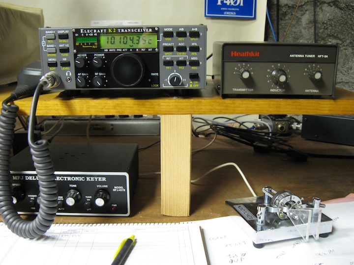
So, here is the "before" picture, with the Heathkit antenna tuner still on-line.
And here is the "after" picture. The Heathkit tuner has migrated upstairs to my office where, together with my smallwonderlabs.com PSK-20 and a zip cord dipole up in the attic, I'm back on PSK31 (see picture here).

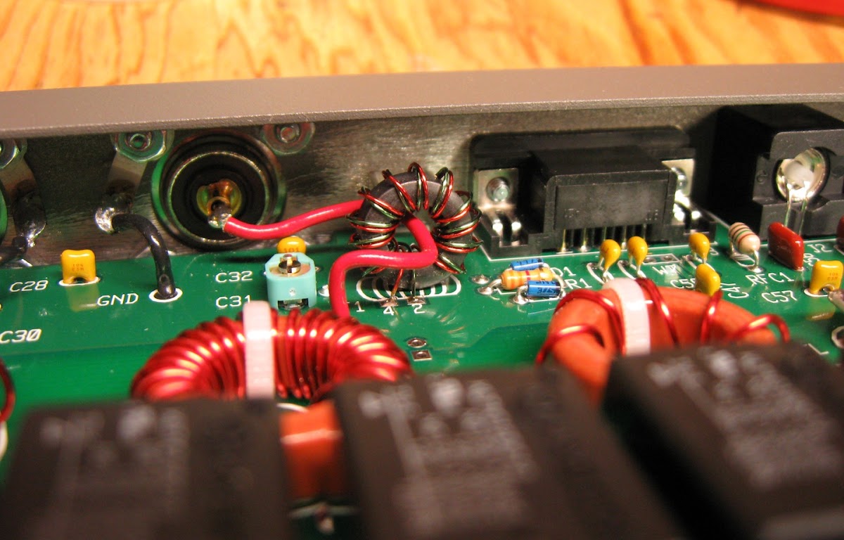
The only glitch in getting the KAT100 on-line was that it was DOA when I first powered it up and connected it to the K2. The Troubleshooting section of the manual directed my attention to Z1 and R5, both in the neighborhood of the CPU, where I found that I had not soldered pin 1! It was the remaining round solder pad after soldering 39 rectangular pads. Anyway, a 2 second soldering job fixed the problem, and the tuner works flawlessly, happily tuning my 40/30 meter random-length end-fed antenna. I really like the memory feature; band changes are now instantaneous.

This was a very enjoyable project! Thanks once again to Elecraft and to W3FPR.

Sunday, March 31, 2013

KAT100 almost completed

Two very good build sessions have brought the KAT100 project pretty close to completion.

Here's a detail of the completed front panel board. Using the slow-but-sure approach, and carefully following the instructions, it was actually pretty easy to get the LEDs lined up.
Here are the RF board and the front panel board bolted together for the first time.
Here's a detail of the bottom view of the RF board and front panel board bolted together. When assembling the K2 and the KSB2, you had to be very careful in mounting the various multi-pin connectors so that the PC board connectors would properly seat. Here, you just plug J101 into P5 unsoldered, bolt the two boards together, and then do all the soldering. It was easy.
Here's a detail of the RF-in line threaded through T1. Came out pretty good, but it would have been easier to thread it through before screwing the back panel on.
Here's a view of the almost completed KAT100. By the way, although the instructions say that the side panels have a finished side and a "lightly painted", i.e., in-side, as shipped, both sides were actually finished; I used a drill-mounted wire brush to scrape off the paint.

What remains to be built are the K2-to-KAT100 communications cable and the power cable, to be followed by alignment, test, and (hopefully, with no glitches) putting the new KAT100 on-line.

Friday, March 29, 2013

Doing the toroids

I have completed installing all the toroidal components. I had wound L1 to L6 while waiting for those missing capacitors to arrive at the beginning of the build. Then, I wound L7 and L8 in sequence.

Here are L1 to L8, ready for tinning and installation.
Here are L1 to L8 installed on the main board. It's worth noting that it took a lot of heat and a lot of solder and a larger tip to successfully heat-strip the #20 wire. I always like to use some very fine grit sand paper on the leads after heat-stripping and before installation.

Winding and installing RFC2 and T1 completed construction of the main board. Back to the small tip for heat-stripping the #26 wire.

Here is a detail of RFC2 installed.
Here is a detail of T1 installed. You can also get a good view of D1 and D2 as well as C31 (mentioned in an earlier post).
I wrapped up today's session by getting started on the front panel board. The next step is to install all the front panel LEDs and I want to be fresh for that.

Sunday, March 24, 2013

Two sessions ... and RFC1 and D1/D2

I had two good build sessions, one yesterday and one today. This post will show two progress views and two build details that I thought were worth documenting. First, the progress views:

Here's the main board at the conclusion of yesterday's build session.
Here's the main board at the conclusion of today's build session.

Yesterday's build session encountered the only two somewhat tricky part insertions so far.

The leads to D1 and D2 need to be bent to 90° right at the body of the diode. Even bending the leads really close to the body, I was unable to get the diodes to sit totally flat again the board (although I got it pretty close).
The instructions for mounting RFC1 read "[the choke] has very fragile leads. Do not pull them." It goes on to warn again excessive soldering time. Well, RFC1's length exceeds the spacing for its mounting holes. I didn't attempt to get the part really close to the board. The picture shows my mounting solution.

Next ... two more toroids to wind, tin all the leads, and move on to mounting L1 to L8.

Thursday, March 21, 2013

Resistors and capacitors and C31

The 7 missing capacitors arrived in the mail yesterday (thumbs up to Elecraft parts folks and the USPS!) and I got back to soldering last night.

The main board is now populated with all its capacitors and all its resistors (with the exception of one resistor on the bottom of the board to be inserted first the next time I fire up the soldering iron). This board sure is spacious!
The directions for inserting C31 read "Orient the flat side of the trimmer as indicated." The indication on the board was clear enough, but, judging from the shape of the part, I wasn't sure which side was the "flat side." Fortunately, Google image search came up with a recent (2010) hi-res picture of the KAT100 main board that clearly showed how C31 (same form factor) was mounted. This detail shows the result.

While waiting for the capacitors to arrive, I wound L1 to L6. It's really easy working with these large toroids and number 20 wire. I've found in this, and previous projects, that winding the toroids is one of the more enjoyable aspects of the project.

Sunday, March 17, 2013

Just started on the KAT100-1

For this year's project, I've decided to build Elecraft's companion antenna tuner for the K2, the KAT100-1. The kit arrived by UPS a few days ago, and I did a complete inventory. The kit was missing the 7 150pF 2000V capacitors, but was otherwise complete. I wrote to the parts folks on Friday, got a nice email back almost immediately, and am expecting the parts to show up in a day or so.

Here's the obligatory picture of the first installed part, C55. One thing that struck me, having built the KSB2 last year (have a look at my blog posting from just a year ago), is how roomy the KAT100-1 board is!
Here's the main board populated with almost all of the capacitors. What's left are the 7 missing capacitors. I like to follow the build order pretty strictly, so I'm now waiting for the caps to come in the mail. In the meantime, I'll probably wind a few of the inductors in my next build session.

The large number of capacitors went in really quickly. The leads for all the caps, and their corresponding holes in the main board, all had the same spacing, so no bending/forming of leads was required; this was a welcome time and effort saver.