
| I wound most of the toroids and went back to stuffing parts into the KPA100 board. It turned out there wasn't much left to stuff to arrive at Initial Test; it was mostly a matter if installing all the ICs and a few of the back-panel connectors. Here's the test setup, including the modified ribbon cable (and accompanying modified plugs on the K2 controller board and the KPA100 board). |
|
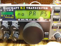
And here's start-up status message ... that was a good feeling! And all voltage tests for Initial Test were well within spec. |
Wednesday, December 29, 2010
KPA100 Initial Test
Sunday, December 26, 2010
Lots of KPA100 Capacitors
Having finally gotten through the large number of capacitors to be stuffed on page 17, I thought it was time for a posting with some pictures.

|
Man, there are a lot of capacitors in this project! Most of it was pretty straightforward, with some exceptions. C26 (a 33pf disc ceramic) lead spacing was wider than the spacing on the board and it was difficult getting the leads bent (and I was worried about breaking them, post-RFC9). Also, a little worried about space for all the inductors amid the forest of 1KV capacitors in the filter area. |

|
There's quite a bit of detailed instructions on p. 15 about stuffing the .01 uf .1" lead spacing capacitors on the bottom of the board. The recommendation was to "remove any U-shaped bends" to ensure that the top of the capacitors are less than 3/16" off the board. Well, I think the bends are necessary to get the hole spacing right, so I left them alone. The caps are small enough so that they fit within 3/16"; see the photo. |
The other instruction for the bottom-mounted capacitors concerned minimizing the amount solder used on the top of the board for these caps. This was necessary because the top-mounted relays all sit directly on top of the solder pads and have a very small, but consistent, clearance above the board. This was easy to do, and there were no problems later on with stuffing the relays.
Finally, I was unable to get RFC9 locally. I wrote to Elecraft's part line this past Monday, and had the replacement RFC in hand in Thursday morning's mail(!). Another great job by Elecraft staff and, for a change, by the USPS.
Taking a break from part-stuffing and am winding inductors, so they will be ready to stuff when I get there in the instructions.
Saturday, December 18, 2010
RFC9
I stuffed most of the resistors and was getting a start on the RFCs. I fiddled with the leads for RFC9, trying to get it to sit flush against the board, long enough to succeed in breaking off one of the leads. It was then that I had a look at the e-mail reflector, did a search on "KPA100 RFC9", and immediately got a hit. Someone was wondering about the same thing and was referred to this document. Well, I wish a reference to this document was included in the KPA100 instructions. It seems that a number of years ago Elecraft stopped using sub-miniature RFCs in favor of miniature RFCs; however, the hole spacing on the KPA100 board fit the sub-miniature parts.

|
The document illustrated how best to form the RFC's leads, which I was able to do for the rest of the sub-miniature parts with no difficulty. You can see it best in RFC7. Well, on Monday, I'll go over to You-Do-It and see if I can find a replacement for RFC9; otherwise, I'll need to write to Elecraft. |
One other construction note: I stuffed D1 to D8 on the bottom of the board, but the instructions did not say whether these are to be soldered on the bottom or top of the board. I looked back at the few bottom-mounted parts I had previously stuffed and, in each case, the instructions were explicit about soldering on the top. Since nothing was said here, I decided to assume that this meant "solder on the bottom", which I did.
Friday, December 17, 2010
Getting The KPA100 Underway

|
My plan was to start work on the KPA100 (Elecraft's 100 watt power amplifier enhancement for the K2) in December and the kit arrived via UPS this past Tuesday. I had kept all the little envelopes and ziplock bags from the K2 kit and decided to sort out all the KPA100 parts while doing the inventory. You can see the result in today's picture. |
There aren't many resistors in this kit, but there are loads of capacitors. They are sorted out in the middle tray in the back, with the small lots in the envelopes to the right. As you can see in the right foreground, there will be quite a few inductors to be wound. All the relays, hardware (nuts, screws, washers, etc.), wire, speaker, fan, and so forth, are sorted out into ziplock bags and are back in the box, awaiting their turn.
Subscribe to:
Posts (Atom)