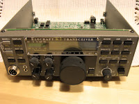
Remarkably few components were needed on the RF board to support the first chunk of "live" testing and alignment. I've included some low resolution pictures (didn't seem to warrant higher resolution, somehow) showing the RF board's connections to the outside world and front and back views of the K2 to date, ready to be powered up and tested.
I encountered the most difficult task to date, and that was getting the tilt stand installed. It extends about 1/2" past its mounting holes on the bottom panel and considerable force was required to compress it sufficiently to, with some luck and persistence, get its mounting screws to drop through the holes.
I also had the most satisfying moment to date, namely seeing how precisely all the connectors lined up and how smoothly the Front Panel and Control Boards plugged into the RF board.
I've decided that if there is a problem with construction, I don't want to know about it today. I plan to power it up tomorrow. Hopefully, there will be a happy post and picture to follow!


