Sunday, April 7, 2013

KAT100 Done!

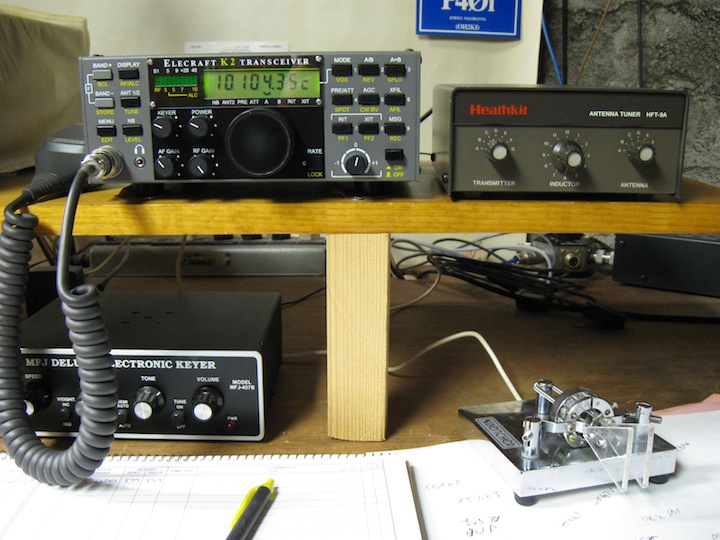
I wrapped up the KAT100 project the other day and put it on-line. Here are a before and after picture.

So, here is the "before" picture, with the Heathkit antenna tuner still on-line.
And here is the "after" picture. The Heathkit tuner has migrated upstairs to my office where, together with my smallwonderlabs.com PSK-20 and a zip cord dipole up in the attic, I'm back on PSK31 (see picture here).

The only glitch in getting the KAT100 on-line was that it was DOA when I first powered it up and connected it to the K2. The Troubleshooting section of the manual directed my attention to Z1 and R5, both in the neighborhood of the CPU, where I found that I had not soldered pin 1! It was the remaining round solder pad after soldering 39 rectangular pads. Anyway, a 2 second soldering job fixed the problem, and the tuner works flawlessly, happily tuning my 40/30 meter random-length end-fed antenna. I really like the memory feature; band changes are now instantaneous.

This was a very enjoyable project! Thanks once again to Elecraft and to W3FPR.

Sunday, March 31, 2013

KAT100 almost completed

Two very good build sessions have brought the KAT100 project pretty close to completion.

Here's a detail of the completed front panel board. Using the slow-but-sure approach, and carefully following the instructions, it was actually pretty easy to get the LEDs lined up.
Here are the RF board and the front panel board bolted together for the first time.
Here's a detail of the bottom view of the RF board and front panel board bolted together. When assembling the K2 and the KSB2, you had to be very careful in mounting the various multi-pin connectors so that the PC board connectors would properly seat. Here, you just plug J101 into P5 unsoldered, bolt the two boards together, and then do all the soldering. It was easy.
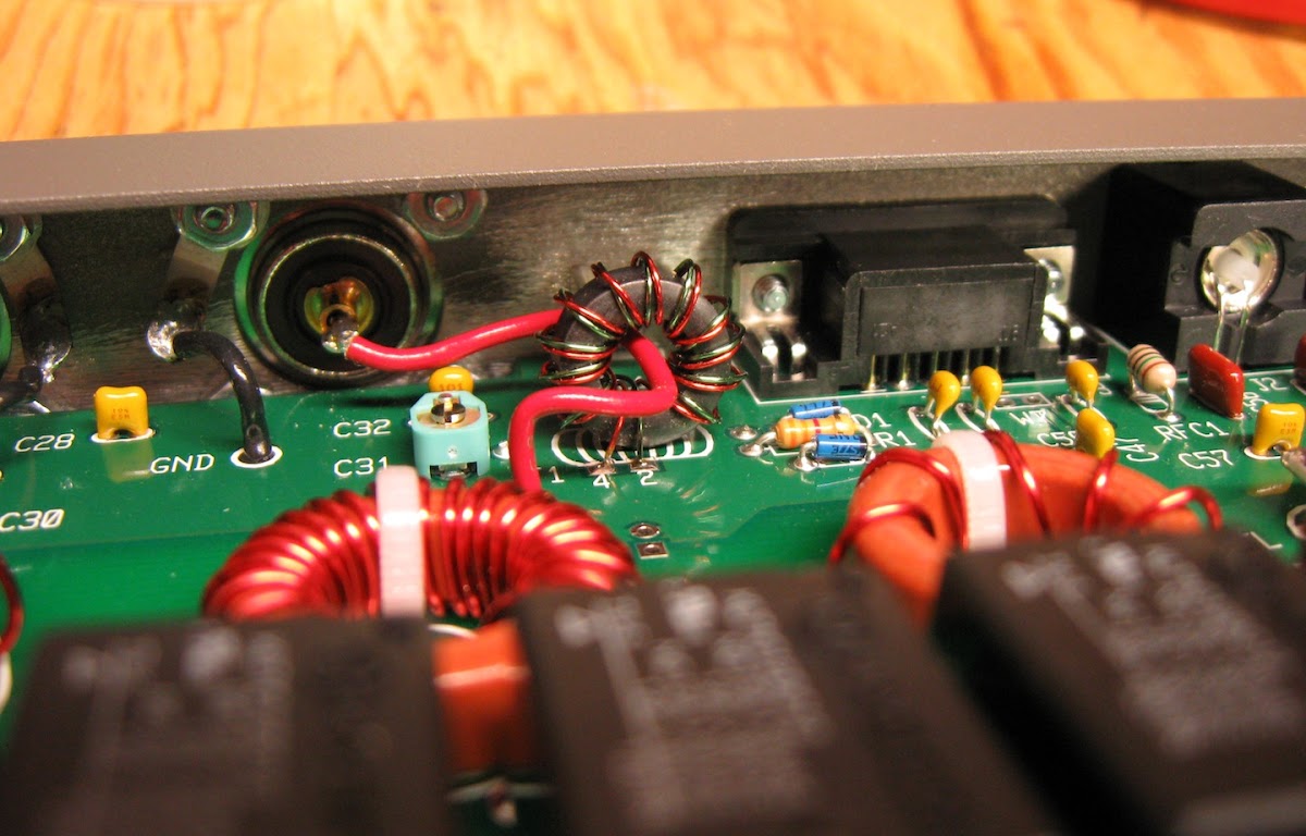
Here's a detail of the RF-in line threaded through T1. Came out pretty good, but it would have been easier to thread it through before screwing the back panel on.
Here's a view of the almost completed KAT100. By the way, although the instructions say that the side panels have a finished side and a "lightly painted", i.e., in-side, as shipped, both sides were actually finished; I used a drill-mounted wire brush to scrape off the paint.

What remains to be built are the K2-to-KAT100 communications cable and the power cable, to be followed by alignment, test, and (hopefully, with no glitches) putting the new KAT100 on-line.

Friday, March 29, 2013

Doing the toroids

I have completed installing all the toroidal components. I had wound L1 to L6 while waiting for those missing capacitors to arrive at the beginning of the build. Then, I wound L7 and L8 in sequence.

Here are L1 to L8, ready for tinning and installation.
Here are L1 to L8 installed on the main board. It's worth noting that it took a lot of heat and a lot of solder and a larger tip to successfully heat-strip the #20 wire. I always like to use some very fine grit sand paper on the leads after heat-stripping and before installation.

Winding and installing RFC2 and T1 completed construction of the main board. Back to the small tip for heat-stripping the #26 wire.

Here is a detail of RFC2 installed.
Here is a detail of T1 installed. You can also get a good view of D1 and D2 as well as C31 (mentioned in an earlier post).
I wrapped up today's session by getting started on the front panel board. The next step is to install all the front panel LEDs and I want to be fresh for that.

Sunday, March 24, 2013

Two sessions ... and RFC1 and D1/D2

I had two good build sessions, one yesterday and one today. This post will show two progress views and two build details that I thought were worth documenting. First, the progress views:

Here's the main board at the conclusion of yesterday's build session.
Here's the main board at the conclusion of today's build session.

Yesterday's build session encountered the only two somewhat tricky part insertions so far.

The leads to D1 and D2 need to be bent to 90° right at the body of the diode. Even bending the leads really close to the body, I was unable to get the diodes to sit totally flat again the board (although I got it pretty close).
The instructions for mounting RFC1 read "[the choke] has very fragile leads. Do not pull them." It goes on to warn again excessive soldering time. Well, RFC1's length exceeds the spacing for its mounting holes. I didn't attempt to get the part really close to the board. The picture shows my mounting solution.

Next ... two more toroids to wind, tin all the leads, and move on to mounting L1 to L8.

Thursday, March 21, 2013

Resistors and capacitors and C31

The 7 missing capacitors arrived in the mail yesterday (thumbs up to Elecraft parts folks and the USPS!) and I got back to soldering last night.

The main board is now populated with all its capacitors and all its resistors (with the exception of one resistor on the bottom of the board to be inserted first the next time I fire up the soldering iron). This board sure is spacious!
The directions for inserting C31 read "Orient the flat side of the trimmer as indicated." The indication on the board was clear enough, but, judging from the shape of the part, I wasn't sure which side was the "flat side." Fortunately, Google image search came up with a recent (2010) hi-res picture of the KAT100 main board that clearly showed how C31 (same form factor) was mounted. This detail shows the result.

While waiting for the capacitors to arrive, I wound L1 to L6. It's really easy working with these large toroids and number 20 wire. I've found in this, and previous projects, that winding the toroids is one of the more enjoyable aspects of the project.

Sunday, March 17, 2013

Just started on the KAT100-1

For this year's project, I've decided to build Elecraft's companion antenna tuner for the K2, the KAT100-1. The kit arrived by UPS a few days ago, and I did a complete inventory. The kit was missing the 7 150pF 2000V capacitors, but was otherwise complete. I wrote to the parts folks on Friday, got a nice email back almost immediately, and am expecting the parts to show up in a day or so.

Here's the obligatory picture of the first installed part, C55. One thing that struck me, having built the KSB2 last year (have a look at my blog posting from just a year ago), is how roomy the KAT100-1 board is!
Here's the main board populated with almost all of the capacitors. What's left are the 7 missing capacitors. I like to follow the build order pretty strictly, so I'm now waiting for the caps to come in the mail. In the meantime, I'll probably wind a few of the inductors in my next build session.

The large number of capacitors went in really quickly. The leads for all the caps, and their corresponding holes in the main board, all had the same spacing, so no bending/forming of leads was required; this was a welcome time and effort saver.

Sunday, March 25, 2012

Almost done ...

I managed to get in some very good construction sessions in the past couple of days and have almost finished up stuffing parts into the KSB2 board. I thought I would post some pictures that folks might find useful.

Here's a view of the bottom of the board; that's where all but one of the resistors are installed. The instructions for prepping the resistor leads and installing the parts were excellent. Overall, I'm finding the KSB2 build instructions to be about the best I've seen from Elecraft so far.
Here's a close-up of the crystals, installed and grounded. Here again, the instructions for grounding the crystals were very good. I also referred back to my posting here on grounding the K2's crystals, which was still helpful.

All that remains to be installed on the KSB2 board are the two transformers and two RFCs; these are all wound and ready to go. Next following that is opening up the K2 and modifying the RF board to accept the new plug-in board.

Thursday, March 22, 2012

Capacitors, Diodes, Resistor Networks

I've managed to put in a small number of hours over the past several days and the project is coming along, as usual, slowly but surely. I'm still checking each component's label and placement on the board two or three times before soldering, and then checking each soldered connection immediately.

Over the weekend, while waiting for the two missing parts to arrive (which they did in the morning USPS delivery on Monday), I wound T1 and T2, so they will be ready when I get there.

You can see in the picture that there were a large number of the small blue caps to be installed; fortunately, for all of them, I was able to follow the initial instruction, and didn't have to bend their leads at all.

Diode installation was no sweat. The instructions were very clear. The right side of the board is so crammed that several of the diodes were not labelled on the board at all, but were very clearly marked in the pictorial in the installation manual. The "check it twice" method caught the fact that I had initially put D4 in in the wrong direction; the cathode goes up, not to the right.

Here's what the KSB2 looks like so far. The right side is crowded. The holes for the cathodes of the two diodes at the extreme right side of the board are actually right at the edge of the board.

Transistors next ...

Friday, March 16, 2012

Adding the KSB2 SSB Adapter

A bit more than a year has gone by since I completed building the KPA100 and the building bug has bit again. I spent a big chunk of this winter someplace warm and I brought my K2 (sans the KPA100), and kind of wished I had had voice capability. So, I decided to add the KSB2 SSB Adapter to my K2.

The kit arrived by UPS yesterday in the late afternoon, and I did the inventory last night. The kit was complete except for one capacitor and one resistor; I wrote to Elecraft about it last night, and the parts have already been shipped as I write this (thanks, Elecraft!!).

Here's the kit, sorted into a variety of containers, and ready for assembly. As you can see, there's really not a lot of parts to this kit. However, as you can see here, the adapter board is pretty small, and there are a lot of small capacitors and 7 crystals, etc., crammed into a pretty small space. Should be interesting!

The KSB2 board is Rev. G, dated 2011. I started construction this afternoon; I couldn't get too far because the missing capacitor is one of the earliest parts to be stuffed (and I really don't want to get ahead of the assembly instructions). Assembly is prefaced with a comment about not needing to straighten the leads on small capacitors, but also to keep them no more than 3mm above the board. However, as the leads were formed on C30 and C36, there was no way the capacitors would be that close to the board; so I straightened the leads (and fortunately did not break them!).

Tuesday, January 18, 2011

KPA100 Completed!!

I haven't posted here for a while, but I have taken a few pictures along the way. Now that the project is done, I thought I would catch up here.

Here's a look at the KPA100 board after the last component had been stuffed, and before mounting it on the heat sink/K2 cover. I put the big 800° tip, the one I use to assemble dipole antennas made out of #14 wire, on my Weller to solder the power transistors to the board. That did the trick very handily.
When assembling T1 and T2, I scouted around the Web looking for pictures. I found some which were helpful, but I decided to take the pictures I wish I had found. This one shows the detail of how T1 was soldered to the board.
Here is a detail of T2's installation, showing both how it is soldered to the board and, in particular, how C83 is mounted on T2's metal frame.
Here is the final alignment and test setup. All procedures in this section of the manual went fine. I made one contact on 40 meters in this configuration. It also became immediately clear as I tested transmitting on the various bands that the KPA100 is quite sensitive to SWR. At this point, I reconfigured my good old Heathkit antenna tuner, which I had just been using to tune my 80/40 meter random antenna, to now tune all my dipoles as well. With SWR now 1.0 to 1 on all bands, the KPA100 happily ran at 100 watts with no power reduction.
Here is the completed K2/100, with the antenna tuner now located in a more convenient place. I made a couple of contacts on 30 meters (HB9 and F5) and ran upstairs to get the camera!

So, I'm at the end of my Elecraft kit construction, for a while anyway. I'll see how the ARRL CW DX contest goes next month, and maybe look into building the KAF2 later this year.

I did not enjoy building the KPA100 to the same extent that I did the K2 and mini-modules. I found it to be fairly grueling, but I'm not sure why; maybe I just needed a longer break before starting construction, or maybe I needed to do it without the February contest staring me in the face. However, the KPA100 works fine "out of the box", and demonstrates again that Elecraft manuals are first rate; you just need to follow the instructions carefully (and especially so when an instruction is in bold font).

Constructing the power cable was a nightmare. Fortunately, this posting to the Elecraft K2 list provided some really helpful hints, especially about installing the fuse connector; I don't think I could have done it without Jay's suggestions. If I were to do this again, I'd buy the pre-assembled cable from Elecraft.

I'd suggest one change to the K2 build that would make KPA100 integration easier, and that is I would include P3 and P6 (RF and power connectors) on the K2's main board as part of the standard K2 build. I don't know what the statistics are on how many K2 builders go on to build the KPA100, but it sure was a nuisance having to disassemble and re-assemble the K2's heat sink to mount these two parts. I would have much preferred to install them as part of K2 construction.

There were no problems with clearance of all those capacitors on the bottom of the board; they all cleared the back of the heat sink with ample margins.

Two surprises: while doing the inventory back at the beginning, I discovered that KPA100 provides a DB9 serial port, allowing the K2 to talk to my computer. I built the serial cable last night and, sure enough, CTWIN can change bands on the K2! The other surprise came up fairly late in construction, and that is that KPA100 provides an on-board SWR bridge and metering. So, my recently built W1 is now off-line. However, I was still glad I built it, since I used it to calibrate the power and SWR metering on the KPA100; it was very handy reading exact power and SWR measurements on my PC!

Thanks to the parts and support folks at Elecraft for their fine help during construction. And thanks as well to Don, W3FPR, for his friendly and very informative support.
Wednesday, December 29, 2010

KPA100 Initial Test

I wound most of the toroids and went back to stuffing parts into the KPA100 board. It turned out there wasn't much left to stuff to arrive at Initial Test; it was mostly a matter if installing all the ICs and a few of the back-panel connectors. Here's the test setup, including the modified ribbon cable (and accompanying modified plugs on the K2 controller board and the KPA100 board).
And here's start-up status message ... that was a good feeling! And all voltage tests for Initial Test were well within spec.

Sunday, December 26, 2010

Lots of KPA100 Capacitors

Having finally gotten through the large number of capacitors to be stuffed on page 17, I thought it was time for a posting with some pictures.

Man, there are a lot of capacitors in this project! Most of it was pretty straightforward, with some exceptions. C26 (a 33pf disc ceramic) lead spacing was wider than the spacing on the board and it was difficult getting the leads bent (and I was worried about breaking them, post-RFC9). Also, a little worried about space for all the inductors amid the forest of 1KV capacitors in the filter area.
There's quite a bit of detailed instructions on p. 15 about stuffing the .01 uf .1" lead spacing capacitors on the bottom of the board. The recommendation was to "remove any U-shaped bends" to ensure that the top of the capacitors are less than 3/16" off the board. Well, I think the bends are necessary to get the hole spacing right, so I left them alone. The caps are small enough so that they fit within 3/16"; see the photo.

The other instruction for the bottom-mounted capacitors concerned minimizing the amount solder used on the top of the board for these caps. This was necessary because the top-mounted relays all sit directly on top of the solder pads and have a very small, but consistent, clearance above the board. This was easy to do, and there were no problems later on with stuffing the relays.

Finally, I was unable to get RFC9 locally. I wrote to Elecraft's part line this past Monday, and had the replacement RFC in hand in Thursday morning's mail(!). Another great job by Elecraft staff and, for a change, by the USPS.

Taking a break from part-stuffing and am winding inductors, so they will be ready to stuff when I get there in the instructions.

Saturday, December 18, 2010

RFC9

I stuffed most of the resistors and was getting a start on the RFCs. I fiddled with the leads for RFC9, trying to get it to sit flush against the board, long enough to succeed in breaking off one of the leads. It was then that I had a look at the e-mail reflector, did a search on "KPA100 RFC9", and immediately got a hit. Someone was wondering about the same thing and was referred to this document. Well, I wish a reference to this document was included in the KPA100 instructions. It seems that a number of years ago Elecraft stopped using sub-miniature RFCs in favor of miniature RFCs; however, the hole spacing on the KPA100 board fit the sub-miniature parts.

The document illustrated how best to form the RFC's leads, which I was able to do for the rest of the sub-miniature parts with no difficulty. You can see it best in RFC7. Well, on Monday, I'll go over to You-Do-It and see if I can find a replacement for RFC9; otherwise, I'll need to write to Elecraft.

One other construction note: I stuffed D1 to D8 on the bottom of the board, but the instructions did not say whether these are to be soldered on the bottom or top of the board. I looked back at the few bottom-mounted parts I had previously stuffed and, in each case, the instructions were explicit about soldering on the top. Since nothing was said here, I decided to assume that this meant "solder on the bottom", which I did.

Friday, December 17, 2010

Getting The KPA100 Underway

My plan was to start work on the KPA100 (Elecraft's 100 watt power amplifier enhancement for the K2) in December and the kit arrived via UPS this past Tuesday. I had kept all the little envelopes and ziplock bags from the K2 kit and decided to sort out all the KPA100 parts while doing the inventory. You can see the result in today's picture.

There aren't many resistors in this kit, but there are loads of capacitors. They are sorted out in the middle tray in the back, with the small lots in the envelopes to the right. As you can see in the right foreground, there will be quite a few inductors to be wound. All the relays, hardware (nuts, screws, washers, etc.), wire, speaker, fan, and so forth, are sorted out into ziplock bags and are back in the box, awaiting their turn.

Tuesday, November 30, 2010

W1 Completed and On-line

Here's the completed W1, on-line and in use for the CQWW CW contest the last weekend in November. The meter worked fine right "out of the box" and I used it throughout the contest for tuning the end-fed wire I use on 40 and 80 meters.

There were no glitches during construction. The only really time-consuming part of the project was winding T1, which I did while waiting for the missing caps to show up in the mail. I also put together a serial cable to try out the software that can be downloaded from the Elecraft web site. At first it seemed like the software didn't work. However, testing using HyperTerm on my PC revealed that the serial cable was picking up RF from the K2; winding the cable several times through a large toroid solved the problem, and the software worked great.

By the way, running 10 watts into dipoles and my 80/40 meter end-fed random antenna resulted in 165 contacts in the CQWW contest, including contacts in Australia and Japan on 20 meters (and thanks to both ops for hanging in there with me to get my call sign correctly)! Still can't decide whether I need additional filters; I'll see how the contest goes next February, I guess.

Tuesday, November 16, 2010

Elecraft W1 Wattmeter/SWR Bridge

My Elecraft W1 kit arrived in the mail yesterday. It weighed 1 pound and was therefore too heavy to be shipped USPS First Class. However, another shipping option was USPS Priority Mail, which arrived here as fast as First Class and was way cheaper than UPS.

I inventoried the kit upon arrival and it was unfortunately missing all 8 .01 uF capacitors. I wrote to Elecraft's parts e-mail, got an immediate response, and just received an automated e-mail telling me that the parts were just shipped USPS First Class ... should be here Thursday.

Here's the W1 kit (minus the missing capacitors) sorted and ready for construction. Immediately after I took this picture, I fired up the soldering iron and stuffed most the resistors and the two resistor packs.

Monday, October 18, 2010

N-gen

I ordered the N-gen kit last Thursday and it arrived in USPS mail today. It was a very simple kit, with very few parts. I guess I still don't understand Elecraft's pricing on this (a tiny fraction of the parts in the K2 at about 8% of the cost), but it was fun to put together and will be a nice tool in my shack.

Here's the N-gen, ready for running through the filter alignment procedure.
Here's a hi-res closeup of the completed N-gen. The MAR-1 was the only component that I had to puzzle over, but finally decided to install it using the SMT technique I used when I built my PSK-20 last year, i.e., I put some solder on each pad first, placed the part, then soldered down one lead, then gronched down and soldered the rest.

The next step will be to align all the filters using Spectrogram and the very detailed procedure described in this document at the late N0SS's archived web site.

Friday, October 8, 2010

Success!

First contact with the new rig: on 20 meters with UA6YH (Alex), east of the Black Sea. My report was 559 ... very satisfying, especially for 10 watts and a not very high dipole!

Thursday, October 7, 2010

"This completes assembly of your K2"

Well, "two or three hours" was a bit optimistic! It actually took quite a while to get through the last four transformers. I was being extra careful about getting the spacing right. T4 turned out to be fairly brutal; getting those two "link" windings into their respective soldering pads right next to T3 was nearly impossible for the size of my fingers.

However, by late afternoon, I completed assembly of the RF board (whew!!) and plugged the three boards together and mounted it all in the case, ready for Integration Test 3 and alignment.
I ran the N6KR method for setting the 4 MHz reference oscillator, which worked really well, and ran through the receiver and transmitter alignment steps a couple of times (last night when I was too darned tired, and then again today when I was fresh and actually read the fine print!!) ... and depicted is the result ... Elecraft K2 S/N 6982.

Actually, I did as much of the alignment as I could. I don't own a noise or signal generator and 10 and 12 meters were so dead there was nothing for me to use to peak the band pass filters. Also, I don't own a dummy load and don't have antennas for all the bands either, so I couldn't peak all the band pass filters by the transmit method either. I plan to build the KPA100 (100 watt module) next (heh ... stay tuned for more blog posts later this year) and will get a dummy load as part of that project. I also will probably get Elecraft's N-GEN noise generator (although I think they charge too much for it!). With noise generator and dummy load in hand, I will be able to complete alignment for the other bands.

Looking forward to getting on 20 meters tomorrow!! Right now ... very satisfied and very tired.

Tuesday, October 5, 2010

Home Stretch

I spent a couple of days just enjoying listening to 40 meters, and had to push myself to disassemble the K2! At that point, I decided to try to push through to finish assembly; there were only a few pages of RF board construction left to go to arrive at Integration Test 3. So, I've put in a lot more daily hours in the past few days and am now close to finishing the RF board.

Having documented my stuffing the first resistor on the Control Board, I thought I would amuse myself by also documenting stuffing the last resistor as well. R44 is the last small component to be stuffed, as well as the last component (except for the PA transistors) to be mounted on the bottom of the board.
So, here's the whole RF board. All that remains to be mounted are 4 transformers, that I still need to wind, and the 2 PA transistors. Although it may not look like that many in the photograph, there were a lot of capacitors to be stuffed, many of which were the tiny ones that needed to have their leads formed to fit the solder pads. The last step in today's construction was really speeded by my having already wound L16 through L24 a week or so ago.

Two or three more hours should see me through to Integration Test and Alignment 3.

Most of the way through page 70 ...